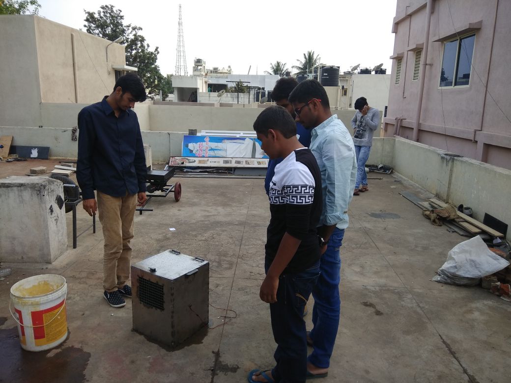
LATEST SOLAR POWER GENERATION PROJECTS
At TECHNOFIST we provide academic projects
based on SOLAR POWER GENERATION with latest papers
implementation. Below mentioned are the list and
abstracts on Android domain. For synopsis and IEEE papers
please visit our head office and get registered.
OUR COMPANY VALUES : Instead of Quantity we prefer Quality, commitment and success.
OUR CUSTOMERS are delighted with the business benefits of the Technofist engineering solutions.
LATEST SOLAR AND POWER GENERATION BASED PROJECT TITLES
-
TECHNOFIST provides SOLAR AND POWER GENERATION projects with latest IEEE concepts and training in Bangalore. We have 12 years experience in delivering SOLAR AND POWER GENERATION based projects. Below mentioned are few latest IEEE transactions on SOLAR AND POWER GENERATION. Technofist is the best institute in Bangalore to carry out SOLAR AND POWER GENERATION based projects for final year academic project purpose. Latest solar and power generation concepts for what is essential for final year engineering and Diploma students which includes Synopsis, Final report and PPT Presentations for each phase according to college format.
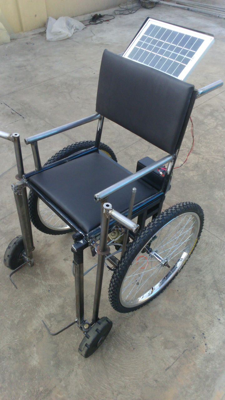
Solar energy generation is one of fastest growing and most promising renewable energy sources of power generation worldwide. The power is generated from Solar Panel, Further this Power is stored in Battery. This category consists of Solar generation project list with abstract/synopsis.Here we provide latest collection of topics developed using latest designs and concepts. Latest solar and power generation concepts for Diploma, Engineering students.
Students of MECH, ECE, CSE , ISE , EEE and Telecommunication Engineering departments, willing to pursue final year project in stream of SOLAR AND POWER GENERATION can download the project titles with abstracts below.
| TSP01 | |
| TSP02 | |
| TSP03 | |
| TSP04 | |
| TSP05 | |
| TSP06 | |
| TSP07 | |
| TSP08 | |
| TSP09 | |
| TSP10 | |
| TSP11 | |
| TSP12 |

CONTACT US
For more information and full ABSTRACT
+91 9008001602
technofist.projects@gmail.com
Technofist provides latest SOLAR POWER GENERATION Projects for final year engineering students in Bangalore | India, SOLAR POWER GENERATION Based Projects with latest concepts are available for final year ece / eee / cse / ise / telecom students , latest titles and abstracts based on SOLAR POWER GENERATION Projects for engineering Students, latest ieee based SOLAR POWER GENERATION project concepts, new ideas on SOLAR POWER GENERATION Projects, SOLAR POWER GENERATION Based Projects for MECHCANICAL, SOLAR POWER GENERATION based Embedded Projects, SOLAR POWER GENERATION latest projects, final year SOLAR POWER GENERATION based project for be students, final year SOLAR POWER GENERATION projects, SOLAR POWER GENERATION training for final year students, real time SOLAR POWER GENERATION based projects, embedded IEEE projects on SOLAR POWER GENERATION, innovative projects on SOLAR POWER GENERATION with classes, lab practice and documentation support.
SOLAR & POWER GENERATION PROJECT CONCEPTS
Solar Power
Is the conversion of energy from sunlight into electricity, either directly using photovoltaics (PV), indirectly using concentrated solar power, or a combination. Concentrated solar power systems use lenses or mirrors and tracking systems to focus a large area of sunlight into a small beam. Photovoltaic cells convert light into an electric current using the photovoltaic effect.
Photovoltaics
Main article: Photovoltaics
Schematics of a grid-connected residential PV power system
A solar cell, or photovoltaic cell (PV), is a device that converts light into electric current using the photovoltaic effect. The first solar cell was constructed by Charles Frits in the 1880s. The German industrialist Ernst Werner von Siemens was among those who recognized the importance of this discovery. In 1931, the German engineer Bruno Lange developed a photo cell using silver selenide in place of copper oxide although the prototype selenium cells converted less than 1% of incident light into electricity. Following the work of Russell Ohl in the 1940s, researchers Gerald Pearson, Calvin Fuller and Daryl Chapin created the silicon solar cell in 1954. early solar cells cost 286 USD/watt and reached efficiencies of 4.5–6%.
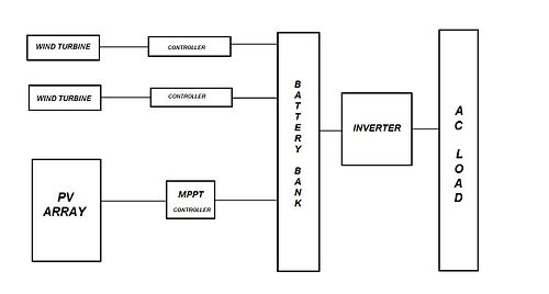
Hybrid renewable energy system
(HRES) are becoming popular as stand-alone power systems for providing electricity in remote areas due to advances in renewable energy technologies and subsequent rise in prices of petroleum products. A hybrid energy system, or hybrid power, usually consists of two or more renewable energy sources used together to provide increased system efficiency as well as greater balance in energy supply.
Completely Renewable Idea
Completely Renewable Hybrid Power Plant (solar, wind, biomass, hydrogen) A hybrid power plant consisting of these four renewable energy sources can be made into operation by proper utilization of these resources in a completely controlled manner. Hybrid Energy Europe-USA. Caffese in Europe introduce hybridizing HVDC transmission with Marine hydro pumped Energy Storage via elpipes. The project of Caffese is 3 marine big lakes producing 1800 GW and transmission with elpipes. A part 1200 GW produce water fuels-wind fuels-solar fuels 210 billion liter year. (IEEE Power and Engineering Society-General Meeting Feb.9,Arpa-E,Doe USA,MSE Italy,European Commission-Energy-Caffese plan and Consortium)
Biomass-wind-fuel cell
Let us consider a load of 100% power supply and there is no renewable system to fulfill this need, so two or more renewable energy system can be combined. For example, 60% from a biomass system, 20% from wind system and the remainder from fuel cells. Thus combining all these renewable energy systems may provide 100% of the power and energy requirements for the load, such as a home or business.
Drawbacks
Most of us already know how a solar/wind/biomass power generating system works, all these generating systems have some or the other drawbacks, like Solar panels are too costly and the production cost of power by using them is generally higher than the conventional process, it is not available in the night or cloudy days. Similarly Wind turbines can’t operate in high or low wind speeds and Biomass plant collapses at low temperatures.
How to Overcome?
So if all the three are combined into one hybrid power generating system the drawbacks can be avoided partially/completely, depending on the control units. As the one or more drawbacks can be overcome by the other, as in northern hemisphere it is generally seen that in windy days the solar power is limited and vice versa and in summer and rainy season the biomass plant can operate in a full flagged so the power generation can be maintained in the above stated condition. The cost of solar panel can be subsided by using glass lenses, mirrors to heat up a fluid, that can rotate the common turbine used by wind and other sources.
Now the question arises what about the winter nights or cloudy winter days with very low wind speeds. Here comes the activity of the Hydrogen. As we know the process of electrolysis can produce hydrogen by breaking water into hydrogen and oxygen, it can be stored; hydrogen is also a good fuel and burns with oxygen to give water. Hydrogen can be used to maintain the temperature of the biomass reservoir in winter so that it can produce biogas in optimum amount for the power generation.
As stated above biogas is a good source in summer; in this period the solar energy available is also at its peak, so if the demand and supply is properly checked and calculated the excess energy can be used in the production of hydrogen and can be stored. In sunny, windy &hot day, the turbine operates with full speed as the supply is maximum, and this excess power can be consumed for the process of manufacturing hydrogen. In winter, the power consumption is also low so the supply limit is low, and obtained with lesser consumption. Driving hybrid cars will disable this outcome.
Thermal plant
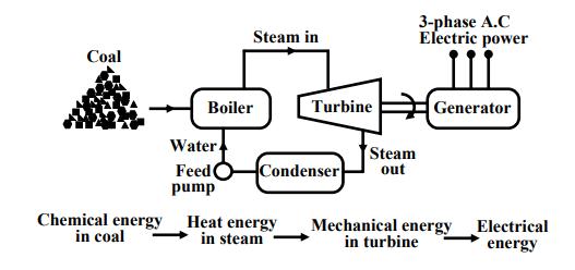
We have seen in the previous section that to generate voltage at 50 Hz we have to run the generator at some fixed rpm by some external agency. A turbine is used to rotate the generator. Turbine may be of two types, namely steam turbine and water turbine. In a thermal power station coal is burnt to produce steam which in turn, drives the steam turbine hence the generator (turbo set). The elementary features of a thermal power plant is shown. In a thermal power plant coil is burnt to produce high temperature and high pressure steam in a boiler. The steam is passed through a steam turbine to produce rotational motion. The generator, mechanically coupled to the turbine, thus rotates producing electricity. Chemical energy stored in coal after a couple of transformations produces electrical energy at the generator terminals as depicted in the figure. Thus proximity of a generating station nearer to a coal reserve and water sources will be most economical as the cost of transporting coal gets reduced. In our country coal is available in abundance and naturally thermal power plants are most popular. However, these plants pollute the atmosphere because of burning of coals. Boiler Turbine Generator Steam in 3-phase A.C Electric power Condenser Water Steam Feed out pump Chemical energy in coal Heat energy in steam Mechanical energy in turbine Electrical energy Basic components of a thermal generating unit. Coal Stringent conditions (such as use of more chimney heights along with the compulsory use of electrostatic precipitator) are put by regulatory authorities to see that the effects of pollution is minimized. A large amount of ash is produced every day in a thermal plant and effective handling of the ash adds to the running cost of the plant. Nonetheless 57% of the generation in out country is from thermal plants. The speed of alternator used in thermal plants is 3000 rpm which means 2-pole alternators are used in such plants
hydel plants
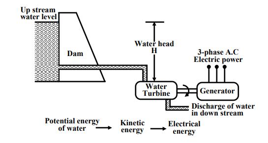
In a hydel power station, water head is used to drive water turbine coupled to the generator. Water head may be available in hilly region naturally in the form of water reservoir (lakes etc.) at the hill tops. The potential energy of water can be used to drive the turbo generator set installed at the base of the hills through piping called pen stock. Water head may also be created artificially by constructing dams on a suitable river. In contrast to a thermal plant, hydel power plants are eco-friendly, neat and clean as no fuel is to be burnt to produce electricity. While running cost of such plants are low, the initial installation cost is rather high compared to a thermal plants due to massive civil construction necessary. Also sites to be selected for such plants depend upon natural availability of water reservoirs at hill tops or availability of suitable Version 2 EE IIT, Kharagpur rivers for constructing dams. Water turbines generally operate at low rpm, so number of poles of the alternator are high. For example a 20-pole alternator the rpm of the turbine is only 300 rpm. Discharge of water in down stream Generator Up stream water level 3-phase A.C Electric power Water head H Dam Water Turbine Potential energy of water Kinetic energy Electrical energy Basic components of a hydel generating unit.
Non conventional
sources of energy The bulk generation of power by thermal, hydel and nuclear plants are called conventional methods for producing electricity. Search for newer avenues for harnessing eco friendly electrical power has already begun to meet the future challenges of meeting growing power demand. Compared to conventional methods, the capacity in terms of MW of each nonconventional plant is rather low, but most of them are eco friendly and self sustainable. Wind power, solar power, MHD generation, fuel cell and power from tidal waves are some of the promising alternative sources of energy for the future.
transmission of power
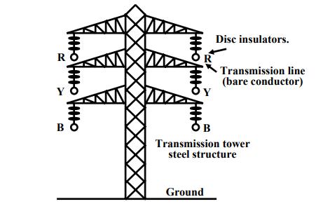
The huge amount of power generated in a power station (hundreds of MW) is to be transported over a long distance (hundreds of kilometers) to load centers to cater power to consumers with the help of transmission line and transmission towers as shown in figure To give an idea, let us consider a generating station producing 120 MW power and we want to transmit it over a large distance.
Let the voltage generated (line to line) at the alternator be 10 kV. Then to transmit 120 MW of power at 10 kV, current in the transmission line can be easily calculated by using power formula circuit (which you will learn in the lesson on A.C circuit analysis) for 3-phases follows: I = 3 L P V cos θ where cos θ is the power factor = 6 3 120×10 3×10×10 ×0.8 ∴ I = 8660 A Instead of choosing 10 kV transmission voltage, if transmission voltage were chosen to be 400 kV, current value in the line would have been only 261.5 A. So sectional area of the transmission line (copper conductor) will now be much smaller compared to 10 kV transmission voltage.
In other words the cost of conductor will be greatly reduced if power is transmitted at higher and higher transmission voltage. The use of higher voltage (hence lower current in the line) reduces voltage drop in the line resistance and reactance. Also transmission losses is reduced. Standard transmission voltages used are 132 kV or 220 kV or 400 kV or 765 kV depending upon how long the transmission lines are. Therefore, after the generator we must have a step up transformer to change the generated voltage (say 10 kV) to desired transmission voltage (say 400 kV) before transmitting it over a long distance with the help of transmission lines supported at regular intervals by transmission towers. It should be noted that while magnitude of current decides the cost of copper, level of voltage decides the cost of insulators. The idea is, in a spree to reduce the cost of copper one can not indefinitely increase the level of transmission voltage as cost of insulators will offset the reduction copper cost.
At the load centers voltage level should be brought down at suitable values for supplying different types of consumers. Consumers may be (1) big industries, such as steel plants, (2) medium and small industries and (3) offices and domestic consumers. Electricity is purchased by different consumers at different voltage level. For example big industries may purchase power at 132 kV, medium and big industries purchase power at 33 kV or 11 kV and domestic consumers at rather low voltage of 230V, single phase. Thus we see that 400 kV transmission voltage is to be brought down to different voltage levels before finally delivering power to different consumers. To do this we require obviously step down transformers.
.jpg)